BRP Lambda to WiFi BRP -firmware for ULA, designed to transmit and display oxygen content (Lambda) values and engine operation parameters (temperature, TPS, etc.) via WiFi to any device (phone, tablet, computer), as well as saving the vehicle operation log in flash adapter memory for further data loading and processing. It is used to create ideal fuel injection maps for your vehicles.
To start using the device, you must perform the following steps:
1. Install the lambda sensor in the exhaust manifold of the engine or install an adapter for the lambda between the manifold and the exhaust pipe, depending on the type of vehicle.
2. Connect the lambda connector and vehicle OBD (diagnostic connector) to the device.
3. Activate the vehicle to power on the OBD, and then on the phone (tablet, computer) in the WiFi network settings you need to discover a new ULA network. Connect to it, the default password is 12345678. If the connection is successful, the WiFi LED will change from red to green.
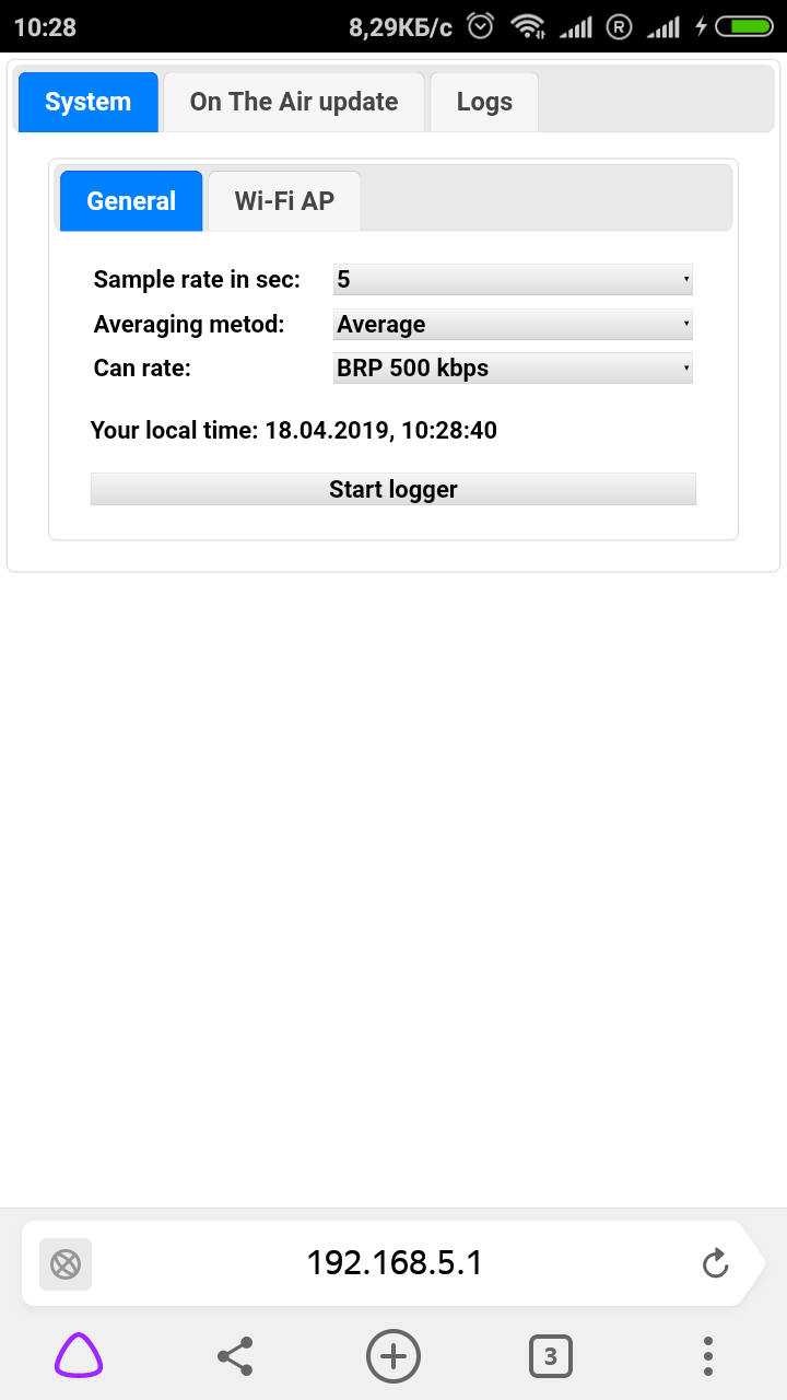
4. In the phone’s browser, enter the link to the device address 192.168.1.5, after which you will s
LAMBDA to CAN
1. Sample rate in sec: - lambda data transmission rate over the CAN bus (5.10 or 20 frames per second).
2. Averaging method: - Lambda data averaging method (RMS, Average, mAverage). The device collects data from the oxygen sensor 800 times per second. Further, groups of 40, 80 or 160 values are processed, respectively, at a selected speed of 20, 10 or 5 logging data. Next, the data is processed through one of the selected filters.
2.1. The Average filter provides for a mathematical summation of 40, 80 or 160 values (depending on the selected logging speed) and finding the average mathematical value for the selected reference period.
2.2. The RMS filter provides for finding the mean square value for the selected reference period.
2.3. The mAverage filter works in the same way as the Average filter, and then the average value is found taking into account the value of the averaging obtained in the past period.
3. Can Rate: - The CAN bus speed of your vehicle (250K, 500K).
4. Can Frame: - Standard (Std) or Extended (Ext) CAN bus address.
5. Can ID (HEX): - hex CAN address, which is used for sending lambda data frames.
Button for controlling the start of heating and data logging Start logger. When you click on this button, the page will automatically open and you will see a work screen with instruments displaying the engine status and lambda values:
Once all the settings have been made according to the protocol of your vehicle, click Save & Restart, the device will reboot to accept your settings and begin work on transferring the lambda data to the CAN bus. At the same time, the ERR LED flashes green, which means warming up the lambda. As soon as it stops flashing and glowing green, the lambda sensor is heated to the required temperature and the device transmits the correct data.
BRP LAMBDA to WiFi
The settings of this mode are almost the same as the Lambda to CAN mode. After clicking the Start logger button you will see the working screen of the engine and lambda instruments:
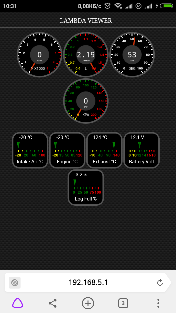
1. RPM - Engine speed.
2. LAMBDA - Indications lambda sensor.
3. TPS - Throttle position angle (throttle knob).
4. IAP - Intake manifold pressure in kPa.
5. Intake Air ° С - Intake manifold (air) temperature in Celsius.
6. Engine ° C - Engine temperature in Celsius.
7. Exhaust ° C - The temperature of the exhaust pipe in Celsius.
8. Battery Volt - Battery Voltage in Volts.
9. Log Full% - The percentage of the memory used by the device to save the log.
The device will start to warm up the sensor and save lambda data and data received by PID requests from the CAN bus. At the same time, the ERR LED will start flashing green, which means that the lambda is warming up. As soon as it stops blinking and starts to glow green, it means that the lambda sensor has warmed up to the required temperature and the device has started collecting data. The operation will stop either when the activity in the CAN bus ends (the ignition is turned off) or when the log memory is completely filled (about 30 minutes at the maximum data collection speed or 2 hours at the minimum speed), while you will automatically be returned to the previous page with settings. In the Logs tab, you can view log data (logging start time).
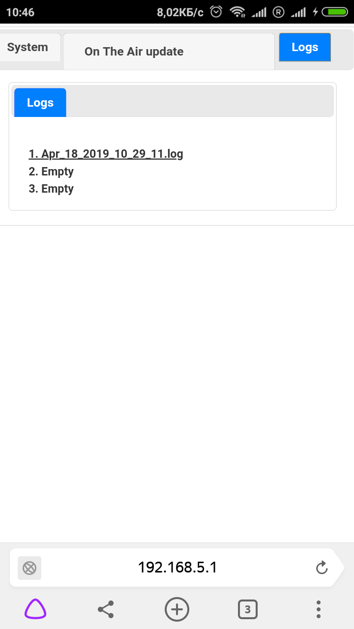
In the Logs tab you will see the log files of your transport, which can be downloaded and opened in Excel for convenient tabular viewing and analysis. |